
Realistic PRO-2006 Hardware Modifications
- Details
- Published on Friday, 03 December 1999 11:36
- Written by David L Norris

Note
- Improper use of these modifications can damage your equipment.
- If you are not highly skilled in electronics, then you may not want to proceed. All modifications require very good soldering skills and a fundamental understanding of radio electronics.
- The Pro-2006 is one of the nicest VHF/UHF receivers made in recent years. If you damage it, then that's your problem. I will not be responsible for your mistakes. These modifications are only a guide, you should know what you are doing before tearing apart any piece of electronics equipment.
Electroluminescent (EL) Backlight Replacement
- White 1.75 x 3.75 inch EL panel from Miller Engineering (I bought mine at GATS from Bob's Model Railroad Supplies)
- Clear, wide packing tape.
- Tools
- Sharp Knife
- Soldering Iron
Parts
Replacing the EL Panel
- Remove the case screws and then the screws which connect the faceplate to the chassis.
- Carefully disconnect all the wires which connect the faceplate to the various boards.
- Remove the screws holding the display board to the faceplate.
- Carefully slide the display board out of the keypad's SIP header.
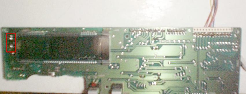
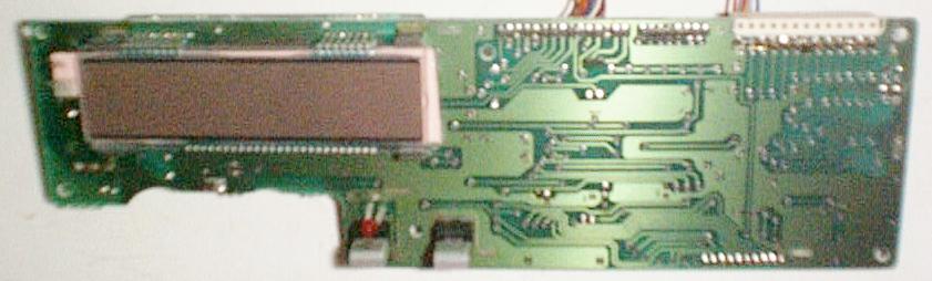
- Desolder the leads on the EL panel and carefully slide it from the LCD panel. (fig 1)
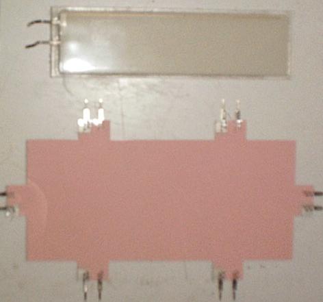
- Use the old EL panel to measure your new material. (fig 2)
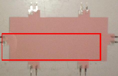
- Take care that you cut the new material so a set of contacts line up with the connections on the display board. (fig 3)
- Test the EL panel for shorts using a continuity tester and/or ohm meter.
- Clean up any frayed edges carefully.
- If you see a dead short then run your fingernail along the cut edge of the EL panel. Particularly the corners.
- If you see a low resistance rather than a short simply leave the material alone on your desk for an hour or so. If you still see a low resistance after some time then check your edges again.
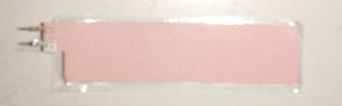
- Seal the EL in the clear packing tape leaving a small extension around the outer edge. (fig 4)
- Carefully slide the sealed EL behind the LCD panel and connect the electrodes to the EL driver contacts on the display board. (fig 5)
- Assemble the radio and test your new display. You may want to test the EL panel before assembling the radio completely.
Figures
EL Removed (EL driver contacts marked in red)
Use old EL material to measure new EL
Take Care to Leave Electrodes on Left Side
EL Cut and Sealed
New EL Installed
Final Assembly (Shown with Icom IC-751)
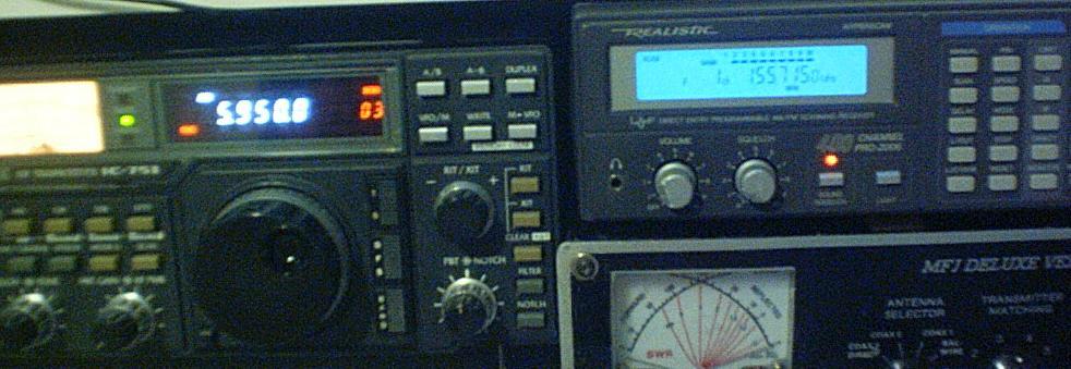
Installing a Patch Panel
Well, you need some place to mount all these new connectors... The battery box seems like a good place to do such a thing. Relocate the 9V battery inside the radio and mount a plastic plate in place of the battery box. Get yourself some panel-mount Phono jacks and attach them as needed. I pulled my patch panel from a dead VCR.
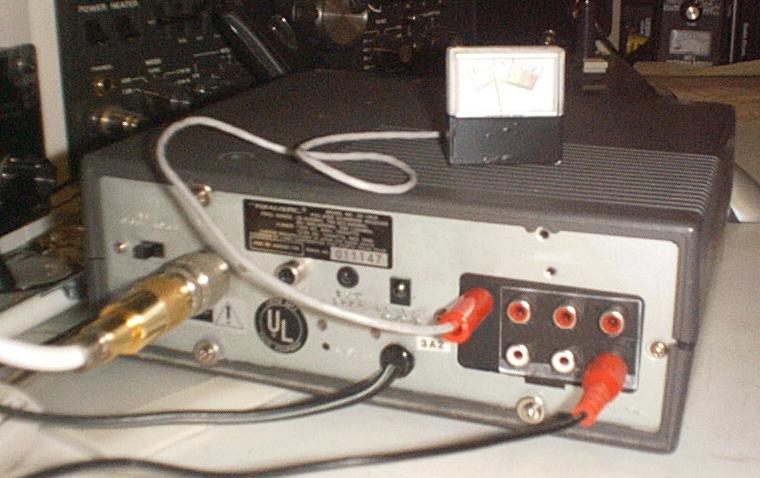
Discriminator Audio Output
- Parts
- A piece of shielded wire
- RCA Panel Connector or some other form of connection to the outside world.
- Tips
- Use tape to collect metal filings and keep the drill bit from ripping parts from the mainboard.
- Locate TP2, next to D33 near the front left of the mainboard
- Drill a hole in the rear panel large enough for your RCA, or similar, connector.
- Run the shielded wire from TP2 to the RCA connector center conductor.
AGC Feedback for S-Meter or Busy indicator
- If you don't know how the IF system works in a superheterodyne receiver, then don't proceed. You could potentially destroy the inter-stage coupling or an IF amp if you do something stupid. Although, the Pro-2006 is fairly solid.
- Parts
- 10 KΩ, 1/8 W resistor
- 0.1 μF Capacitor

- Remove top cover (if it isn't already falling off due to the poor design)
- Locate D33 on the main board
- Solder 10 KΩ resistor to the anode of D33. The anode is the bottom side of the diode in my receiver. This is not TP2!
- Solder the 0.1 μF capacitor between the now open end of the 10 KΩ resistor and a ground (GND) connection. Make sure it is really ground or you may send RF into who knows where.
- The junction of the 10 KΩ resistor and 0.1 μF capacitor follows the AGC voltage.
- You can either connect this to a rear-panel jack. Or, you can run this output directly to a metering circuit.
- AGC Output
- Output is a negative voltage for no signal.
- Output is a positive voltage when a signal is present, increasing with signal strength.
- A 1 Volt full scale panel meter might make a good signal meter.
Relative Signal Strength Meter (Negative Bias)
Assembly

- Parts
- 1/4 W resistor
- PNP Audio Amplifier: NTE159 or similar (I used a CS9012H, whatever that is)
- A 1 Volt meter of some sort.
The resistor is whatever value you need to take the meter off of the peg. I used a 50K rheostat (i.e. wiper tied to one side of the fixed portion). The transistor is whatever you have in the junk drawer, carpet, stuck to the bottom of your shoe, etc. The meter can be anything that resembles a signal meter. You might want to mount it upside down since the meter will move backward from what you expect.
5 Volts may be taken from the LM7805 voltage regulator located next to the power transformer on the main board.
Adjustment

Before you freak out! The meter movement will operate backwards from what you may be used to. Full signal strength will be approx. 0 volt, no signal will be approx. 1 volt. This can be more useful in some situations. When you turn off power to the receiver, the meter will read OVER, or full scale.
Relative Signal Strength Meter (Positive Bias)
Assembly

- Parts
- 1/4 W resistor
- NPN Audio Amplifier: NTE123AP or similar (I used a CS9014F, whatever that is)
- A 1 Volt meter of some sort.
The resistor is whatever value you need to take the meter to full deflection without slamming the peg. A 50K rheostat should be sufficient to allow for adjustment. The transistor can be whatever you have in the junk drawer, carpet, stuck to the bottom of your shoe, etc. The meter can be anything that resembles a signal meter.
5 Volts may be taken from the LM7805 voltage regulator located next to the power transformer on the main board.
Adjustment

The meter movement will give a relative strength indication of stronger stations. Full signal strength will be approx. 1 volt, no signal will be approx. 0 volt. When you turn off power to the receiver, the meter will read 0.